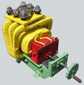
Magnetic circuit production of amorphous nanocrystalline alloys is also possible
Standard Parameters and Dimensions
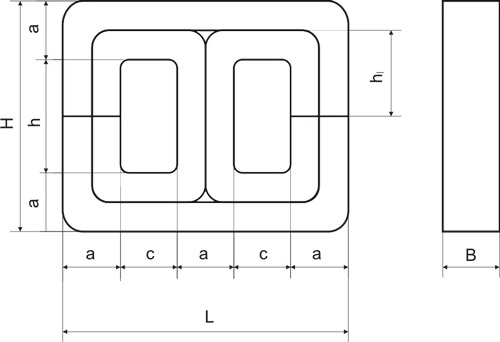
Magnetic circuits are produced according to Drawing 1, Table 1 and 2 out of hoop steel:
- of Grade 3413, ГОСТ 21427.1-83, with a thickness of 0.35 mm for power line frequency of 50 Hz;
- of Grade 3422, ГОСТ 21427.4-78, with a thickness of 0.15 mm for power line frequency of 400 Hz;
- Chamfering 0.1х450 is allowed on core rod butt ends;
- Outer core rod displacement relative to each other for the value К in defined position of middle core rod is allowed.
Magnetic circuit surfaces except specified 3, 2 are covered with enamel ЭЭП-140 of light grey colour. Use of enamels of other brands is allowed.
Table 1
| Magnetic circuit reference designation |
К |
a |
h |
h1 |
c |
L*
| H*
| B |
Rmax
| Magnetic circuit weight, kg |
| Nomin. |
Extr. dev. |
Rmax |
Nomin. |
Nomin. |
Nomin. |
Extr. dev. |
| ТЛ12,5х20-25-0,35-50 |
+0,3 |
12,5 |
+0,24
-0,43 |
25,0 |
12,5 |
25 |
87,5 |
50,0 |
20 |
+0,84 |
1,2 |
0,485 |
| ТЛ12,5х20-29-0,35-50 |
29,0 |
12,5 |
54,0 |
0,505 |
| ТЛ12,5х20-33-0,35-50 |
33,0 |
16,5 |
58,0 |
0,525 |
| ТЛ12,5х20-38,5-0,35-50 |
38,5 |
16,5 |
63,6 |
0,550 |
| ТЛ12,5х20-440,35-50 |
44,0 |
22,0 |
69,0 |
0,580 |
| |
| ТЛ16х25-32-0,35-50 |
+0,5 |
16,0 |
+0,24
-0,43 |
32,0 |
16,0 |
32 |
112 |
64,0 |
25 |
+0,84 |
1,3 |
1,000 |
| ТЛ16х25-37-035-50 |
37,0 |
16,0 |
69,0 |
1,050 |
| ТЛ16х25-42-0,35-50 |
42,0 |
|
74,0 |
1,100 |
| ТЛ16х25-49-0,35-50 |
49,0 |
21,0 |
81,0 |
1,180 |
| ТЛ16х25-56-0,35-50 |
56,0 |
28,0 |
88,0 |
1,260 |
| |
| ТЛ20х32-40-0,35-50 |
+0,7 |
20 |
+0,28
-0,52 |
40,0 |
20,0 |
40 |
140 |
80,0 |
32 |
+1,0 |
1,4 |
1,960 |
| ТЛ20х32-47-0,35-50 |
47,0 |
20,0 |
87,0 |
2,070 |
| ТЛ20х32-54-0,35-50 |
54,0 |
27,0 |
94,0 |
1,170 |
| ТЛ20х32-62-0,35-50 |
62,0 |
27,0 |
102,0 |
2,320 |
| ТЛ20х32-70-0,35-50 |
70,0 |
35,0 |
110,0 |
2,480 |
| |
| ТЛ25х40-50-0,35-50 |
+,9 |
25 |
+0,28
-0,52 |
50,0 |
25,0 |
50 |
175 |
100,0 |
40 |
+1,0 |
1,5 |
3,82 |
| ТЛ25х40-58-0,35-50 |
58,0 |
25,0 |
108,0 |
3,96 |
| ТЛ25х40-66-0,35-50 |
66,0 |
33,0 |
116,0 |
4,15 |
| ТЛ25х40-77-0,35-50 |
77,0 |
33,0 |
127,0 |
4,45 |
| ТЛ25х40-88-0,35-50 |
88,0 |
44,0 |
138,0 |
4,75 |
| |
| ТЛ32х40х64-0,35-50 |
+1,0 |
32 |
+0,34
-0,62 |
64 |
32 |
64 |
224 |
128 |
40 |
+1,0 |
|
6,10 |
| ТЛ32х40х74-0,35-50 |
74 |
32 |
138 |
6,45 |
| ТЛ32х40х84-0,35-50 |
84 |
42 |
148 |
6,80 |
| ТЛ32х40х97-0,35-50 |
97 |
42 |
161 |
7,25 |
| ТЛ32х40х110-0,35-50 |
110 |
55 |
174 |
7,65 |
Table 2
| Magnetic circuit reference designation |
К |
a |
h |
h1 |
c |
L* |
H* |
B |
Rmax |
Magnetic circuit weight, kg |
| Nomin. |
Extr. dev. |
Nomin. |
Nomin. |
Nomin. |
Nomin. |
Extr. dev. |
| ТЛ5х10-14-0,15-400 |
0,4 |
5,0 |
+0,16 -0,30 |
14 |
7 |
14 |
43,0 |
24 |
10,0 |
+0,58 |
0,5 |
0,049 |
| ТЛ5х10-16-0,15-400 |
16 |
7 |
26 |
0,051 |
| ТЛ5х10-18-0,15-400 |
18 |
9 |
28 |
0,053 |
| ТЛ5х10-21-0,15-400 |
21 |
9 |
31 |
0,057 |
| ТЛ5х10-24-0,15-400 |
24 |
12 |
34 |
0,066 |
| |
| ТЛ6,5х10-16-0,15-400 |
0,4 |
6,5 |
+0,20 -0,36 |
16 |
8 |
16 |
51,5 |
29 |
10,0 |
+0,58 |
0,6 |
0,072 |
| ТЛ6,5х10-18-0,15-400 |
18 |
8 |
31 |
0,075 |
| ТЛ6,5х10-20-0,15-400 |
20 |
10 |
33 |
0,078 |
| ТЛ6,5х10-23-0,15-400 |
23 |
10 |
36 |
0,083 |
| ТЛ6,5х10-26-0,15-400 |
26 |
13 |
39 |
0,087 |
| |
| ТЛ8х12,5-18-0,15-400 |
0,4 |
8,0 |
+0,20 -0,36 |
18 |
9 |
18 |
60, |
34 |
12,5 |
+,70 |
0,7 |
0,120 |
| ТЛ8х12,5-21-0,15-400 |
21 |
9 |
37 |
0,151 |
| ТЛ8х12,5-24-0,15-400 |
24 |
12 |
40 |
0,163 |
| ТЛ8х12,5-28-0,15-400 |
28 |
12 |
44 |
0,172 |
| ТЛ8х12,5-32-0,15-400 |
32 |
16 |
48 |
0,170 |
| |
| ТЛ10х16-20-0,15-400 |
0,4 |
10,0 |
+0,20 -0,36 |
20,0 |
10,0 |
20 |
70,0 |
40,0 |
16 |
+0,7 |
0,8 |
0,240 |
| ТЛ10х16-23-0,15-400 |
23,0 |
10,0 |
43,0 |
0,250 |
| ТЛ10х16-26-0,15-400 |
26,0 |
13,0 |
46,0 |
0,260 |
| ТЛ10х16-31-0,15-400 |
31,0 |
13,0 |
51,0 |
0,275 |
| ТЛ10х16-36-0,15-400 |
36,0 |
18,0 |
56,0 |
0,290 |
| |
| ТЛ12,5х20-25-0,15-400 |
0,5 |
12,5 |
+0,24 -0,43 |
25,0 |
12,5 |
25 |
87,5 |
50 |
20 |
+0,84 |
0,9 |
0,470 |
| ТЛ12,5х20-29-0,15-400 |
29,0 |
12,5 |
54 |
0,490 |
| ТЛ12,5х20-33-0,15-400 |
33,0 |
16,5 |
58 |
0,510 |
| ТЛ12,5х20-38-0,15-400 |
38,5 |
16,5 |
63,5 |
0,525 |
| ТЛ12,5х20-44-0,15-400 |
44,0 |
22,0 |
69 |
0,560 |
| |
| ТЛ16х25-32-0,15-400 |
0,6 |
16,0 |
+0,24
-0,43 |
32,0 |
16,0 |
32 |
112 |
64,0 |
25 |
+0,84 |
1,0 |
0,970 |
| ТЛ16х25-37-0,15-400 |
37,0 |
16,0 |
69,0 |
1,020 |
| ТЛ16х25-42-0,15-400 |
42,0 |
21,0 |
74,0 |
1,070 |
| ТЛ16х25-49-0,15-400 |
49,0 |
21,0 |
81,0 |
1,140 |
| ТЛ16х25-56-0,15-400 |
56,0 |
28,0 |
88,0 |
1,220 |
| |
| ТЛ20х32-40-0,15-400 |
0,7 |
20 |
+0,28
-0,52 |
40,0 |
20,0 |
40 |
140 |
80,0 |
32 |
+1,0 |
1,1 |
1,900 |
| ТЛ20х32-47-0,15-400 |
47,0 |
20,0 |
87,0 |
2,000 |
| ТЛ20х32-54-0,15-400 |
54,0 |
27,0 |
94,0 |
2,100 |
| ТЛ20х32-62-0,15-400 |
62,0 |
27,0 |
102,0 |
2,250 |
| ТЛ20х32-70-0,15-400 |
70,0 |
35,0 |
110,0 |
2,400 |
| |
| ТЛ25х40-50-0,15-400 |
+0,8 |
25 |
+0,28
-0,52 |
50,0 |
25,0 |
50 |
175 |
100,0 |
40 |
1,0 |
1,2 |
3,700 |
| ТЛ25х40-58-0,15-400 |
58,0 |
25,0 |
108,0 |
3,850 |
| ТЛ25х40-66-0,15-400 |
66,0 |
33,0 |
116,0 |
4,00 |
| ТЛ25х40-77-0,15-400 |
77,0 |
33,0 |
127,0 |
4,400 |
| ТЛ25х40-88-0,15-400 |
88,0 |
44,0 |
138,0 |
4,60 |
| |
| ТЛ32х40-64-0,15-400 |
+1,0 |
32 |
+0,34-0,62 |
64 |
32 |
64 |
224 |
128 |
40 |
+1,0 |
1,3 |
5,900 |
| ТЛ32х40-74-0,15-400 |
74 |
32 |
138 |
6,250 |
| ТЛ32х40-84-0,15-400 |
84 |
42 |
148 |
6,600 |
| ТЛ32х40-97-0,15-400 |
97 |
42 |
161 |
7,000 |
| ТЛ32х40-110-0,15-400 |
110 |
55 |
174 |
7,600 |
1.2. Magnetic circuit reference designation consists of initial letters of words "three-phase" (T), "strap" (Л) and figures, which designate accordingly rod dimensions, aperture height, band thickness and frequency, at which magnetic circuit is inspected for compliance with requirements of existing standard.
Specification
2.1.1 General requirements
2.1.1. Magnetic circuit should be produced according to the requirements of existing standard.
2.1.2. Materials and semifinished goods used during magnetic circuit production should have appropriate documentation, which confirms their operability in conditions at least equal to the requirements of existing standard.
2.2. Design requirements
2.2.1. Magnetic circuits design and dimensions should comply with Drawing 1 and Table 1 and 2.
2.2.2. Magnetic circuit surface should be without any dirt marks, dints and other mechanical damages and also without corrosion marks.
2.2.3. Magnetic circuits should be monolithic, butt end opening is not allowed.
Note: 1. Gaps between plates are allowed in core mass.
2. Plates recess by width up to 5% of rod thickness is allowed.
3. Glueing of plates, which are separated during magnetic circuit butt end depreservation, with БФ-4 glue according to ГОСТ 12127-74 or equivalent is allowed by consumer.
2.2.4. Magnetic circuit weight should comply with the data specified in Table 1 and 2.
Required Electrical Parameters
2.3.1. Excitation current value and power loss of magnetic circuits should comply with data specified in Table 3 for magnetic circuits with frequency of 50 Hz and in Table 4 for magnetic circuits with frequency of 400 Hz.
Table 3
| Magnetic circuit dimension type |
Induction,,
Wb/m2 |
Current value, A, not more than |
Power loss, W, not more than |
Impressed voltage, phase, V |
Winding turn number W1=W2 |
Winding wire diameter,
mm |
| ТЛ12,5х20-25 |
1,5 |
3х0,036 |
- |
73,5 |
950 |
0,2 |
| ТЛ12,5х20-29 |
3х0,038 |
| ТЛ12,5х20-33 |
3х0,040 |
| ТЛ12,5х20-38,5 |
3х0,042 |
| ТЛ12,5х20-44 |
3х0,044 |
| |
| ТЛ16х25-32 |
1,5 |
3х0,070 |
- |
73,5 |
591 |
0,29 |
| ТЛ16х25-37 |
3х0,073 |
| ТЛ16х25-42 |
3х0,076 |
| ТЛ16х25-49 |
3х0,081 |
| ТЛ16х25-56 |
3х0,086 |
| |
| ТЛ20х32-40 |
1,5 |
3х0,130 |
5,0 |
73,5 |
370 |
0,44 |
| ТЛ20х32-47 |
3х0,137 |
5,2 |
| ТЛ20х32-54 |
3х0,144 |
5,5 |
| ТЛ20х32-62 |
3х0,153 |
5,8 |
| ТЛ20х32-70 |
3х0,162 |
6,1 |
| |
| ТЛ25х40-50 |
1,45 |
3х0,215 |
|
73,5 |
245 |
0,8 |
| ТЛ25х40-58 |
3х0,225 |
| ТЛ25х40-66 |
3х0,235 |
| ТЛ25х40-77 |
3х0,250 |
| ТЛ25х40-88 |
3х0,267 |
| |
| ТЛ32х40х64 |
|
|
|
73,5 |
198 |
1,0 |
| ТЛ32х40х74 |
| ТЛ32х40х84 |
| ТЛ32х40х97 |
| ТЛ32х40х110 |
Table 4
| Magnetic circuit dimension type |
Induction,
Wb/m2 |
Current value, A, not more than |
Power loss, W, not more than |
Impressed voltage, phase, V |
Winding turn number W1=W2 |
Winding wire diameter,
mm |
| ТЛ5х10-14 |
1,4 |
3х0,058 |
- |
73,5 |
655 |
0,11 |
| ТЛ5х10-16 |
3х0,060 |
| ТЛ5х10-18 |
3х0,062 |
| ТЛ5х10-21 |
3х0,065 |
| ТЛ5х10-24 |
3х0,068 |
| |
| ТЛ6,5х10-16 |
1,4 |
3х0,080 |
- |
73,5 |
508 |
0,15 |
| ТЛ6,5х10-18 |
3х0,082 |
| ТЛ6,5х10-20 |
3х0,084 |
| ТЛ6,5х10-23 |
3х0,07 |
| ТЛ6,5х10-26 |
3х0,090 |
| |
| ТЛ8х12,5-18 |
1,4 |
3х0,125 |
3,9 |
73,5 |
327 |
0,21 |
| ТЛ8х12,5-21 |
3х0,130 |
4,1 |
| ТЛ8х12,5-24 |
3х0,135 |
4,3 |
| ТЛ8х12,5-28 |
3х0,140 |
4,6 |
| ТЛ8х12,5-32 |
3х0,145 |
4,9 |
| |
| ТЛ10х16-20 |
1,4 |
3х0,210 |
6,9 |
73,5 |
204 |
0,35 |
| ТЛ10х16-23 |
3х0,217 |
7,2 |
| ТЛ10х16-26 |
3х0,225 |
7,6 |
| ТЛ10х16-31 |
3х0,232 |
8,2 |
| ТЛ10х16-36 |
3х0,240 |
8,8 |
| |
| ТЛ 12,5х20-25 |
1,32 |
3х0,290 |
11,8 |
73,5 |
139 |
0,51 |
| ТЛ 12,5х20-29 |
3х0,300 |
12,4 |
| ТЛ 12,5х20-33 |
3х0,310 |
13,1 |
| ТЛ 12,5х20-38,5 |
3х0,320 |
13,8 |
| ТЛ 12,5х20-44 |
3х0,330 |
14,6 |
| |
| ТЛ16х25-32 |
1,13 |
3х0,330 |
17,8 |
73,5 |
102 |
0,64 |
| ТЛ16х25-37 |
3х0,342 |
18,6 |
| ТЛ16х25-42 |
3х0,355 |
19,5 |
| ТЛ16х25-49 |
3х0,372 |
20,8 |
| ТЛ16х25-56 |
3х0,390 |
22,2 |
| |
| ТЛ20х32-40 |
0,96 |
3х0,380 |
24,4 |
73,5 |
76 |
0,80 |
| ТЛ20х32-47 |
3х0,395 |
25,9 |
| ТЛ20х32-54 |
3х0,410 |
27,5 |
| ТЛ20х32-62 |
3х0,427 |
29,2 |
| ТЛ20х32-70 |
3х0,445 |
31,0 |
| |
| ТЛ25х40-50 |
0,81 |
3х0,450 |
33,6 |
73,5 |
57 |
0,93 |
| ТЛ25х40-58 |
3х0,470 |
35,5 |
| ТЛ25х40-66 |
3х0,490 |
37,5 |
| ТЛ25х40-77 |
3х0,517 |
40,0 |
| ТЛ25х40-88 |
3х0,545 |
42,0 |
| |
| ТЛ32х40х64 |
0,73 |
3х0,490 |
44,5 |
73,5 |
49 |
1,16 |
| ТЛ32х40х74 |
3х0,515 |
47,2 |
| ТЛ32х40х84 |
3х0,540 |
50,0 |
| ТЛ32х40х97 |
3х0,570 |
53,0 |
| ТЛ32х40х110 |
3х0,600 |
56,0 |